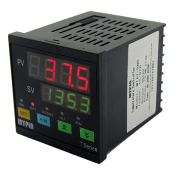
Auto Tuning Pid Controller
- Pid Controller Pdf
- Auto Tuning Pid Controller 2
- Auto Tuning Pid Controller For Sale
- Auto Tuning Pid Controller Manual
“PID auto-tuning” or “PID self-tuning” controllers are designed to simplify matters by choosing their own PID tuning parameters based on some sort of automated analysis of the controlled process’s behavior. Jul 01, 2019 The process of finding value of these parameters is called 'tuning'. PID controller can manually tuning and auto-tuning. Manually tuning: This method requires experienced personnel; Auto-tuning: the tuning is done by a software. I implemented Auto-tuning library for position and speed of DC motor (see the source code) using Relay On/Off method. Simulink Control Design provides several approaches to tuning Simulink blocks, such as Transfer Fcn and PID Controller blocks. Introduction to Model-Based PID Tuning in Simulink Use PID Tuner for interactive tuning of PID gains in a Simulink model containing a PID Controller or PID Controller (2DOF) block.
- I 5oc Tar temperature (c) Result obtained by the settings of the auto-tuning FIG. Application to temperature control of a heat exchanger. Resultant closed-loop response is stable enough as shown in Fig. CONCLUSIONS A new idea for automatic tuning of the PID controlparameters, auto-tuning, has been proposed.
- Jul 24, 2018 Now that we have this model, we can use it to tune a PID controller that will work to control the physical system. PID tuning can be thought of in two ways: Adjusting the three path gains (Kp, Ki.
How PID Autotuning Works
To use PID autotuning, configure and deploy one of the PID autotuner blocks, Closed-Loop PID Autotuner or Open-Loop PID Autotuner.
Autotuning Process
Pid Controller Pdf
The PID autotuner blocks work by performing a frequency-response estimation experiment. The blocks inject test signals into your plant and tune PID gains based on an estimated frequency response.
The following schematic diagram illustrates generally how a PID autotuner block fits into a control system.

Until the autotuning process begins, the autotuner block relays the control signal directly from u to the plant input at u+Δu. In that state, the module has no effect on the performance of your system.
When the autotuning process begins, the block injects a test signal at u out to collect plant input-output data and estimate frequency response in real time.
If you use the Open-Loop PID Autotuner block, the block opens the feedback loop between u and u+Δu for the duration of the estimation experiment. It injects into u+Δu a superposition of sinusoidal signals at frequencies [1/3, 1, 3, 10]ωc, where ωc is your specified target bandwidth for tuning. For nonintegrating plants, the block can also inject a step signal to estimate the plant DC gain. All test signals are injected on top of the nominal plant input, which is the value of the signal at u when the experiment begins.
If you use the Closed-Loop PID Autotuner block, the plant remains under control of the PID controller with its current gains during the experiment. Closed-loop tuning uses sinusoidal test signals at the frequencies [1/10,1/3, 1, 3, 10]ωc.
Auto Tuning Pid Controller 2
When the experiment ends, the block uses the estimated frequency response to compute PID gains. The tuning algorithm aims to balance performance and robustness while achieving the control bandwidth and phase margin that you specify. You can configure logic to transfer the tuned gains from the block to your PID controller, allowing you to validate closed-loop performance in real time.
Workflow for PID Autotuning
The following steps provide a general overview of the workflow for PID autotuning.
Incorporate a PID autotuner block into your system, as shown in the schematic diagram.
Configure the start/stop signal that controls when the tuning experiment begins and ends. You can use this signal to initiate the PID autotuning process at any time. When you stop the experiment, the block returns tuned PID gains.
Specify controller parameters such as controller type and the target bandwidth for tuning.
Configure experiment parameters such as the amplitudes of the perturbations injected during the frequency-response experiment.
Start the autotuning process using the start/stop signal, and allow it to run long enough to complete the frequency-response estimation experiment.
Stop the autotuning process. When the experiment stops, the autotuner computes and returns tuned PID gains.
Transfer the tuned gains from the block to your PID controller. You can then validate the performance of the tuned controller in Simulink® or in real time.
Mobile DJs will probably want to get all-in-one controllers, easy to transport and install anywhere. Can i use pioneer sb3 on traktor pro.
For detailed information on performing each of these steps, see:
Auto Tuning Pid Controller For Sale

See Also
Closed-Loop PID AutotunerOpen-Loop PID Autotuner